
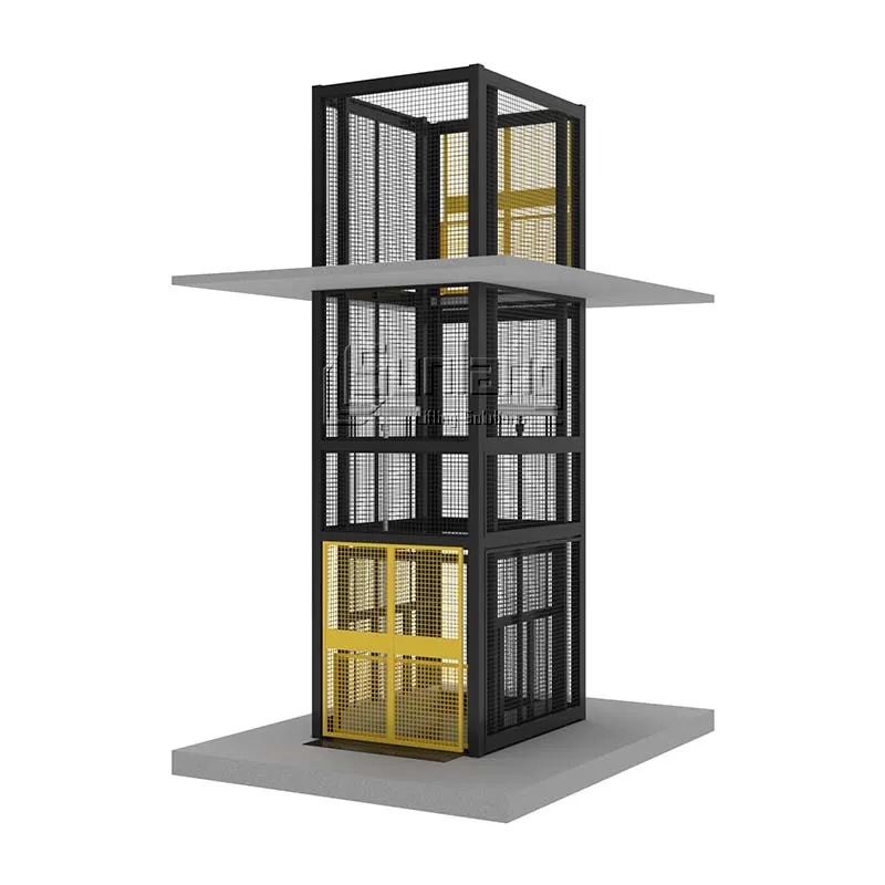
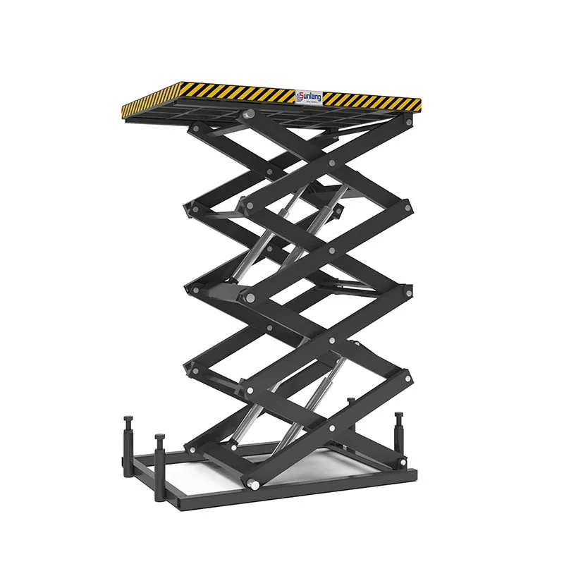
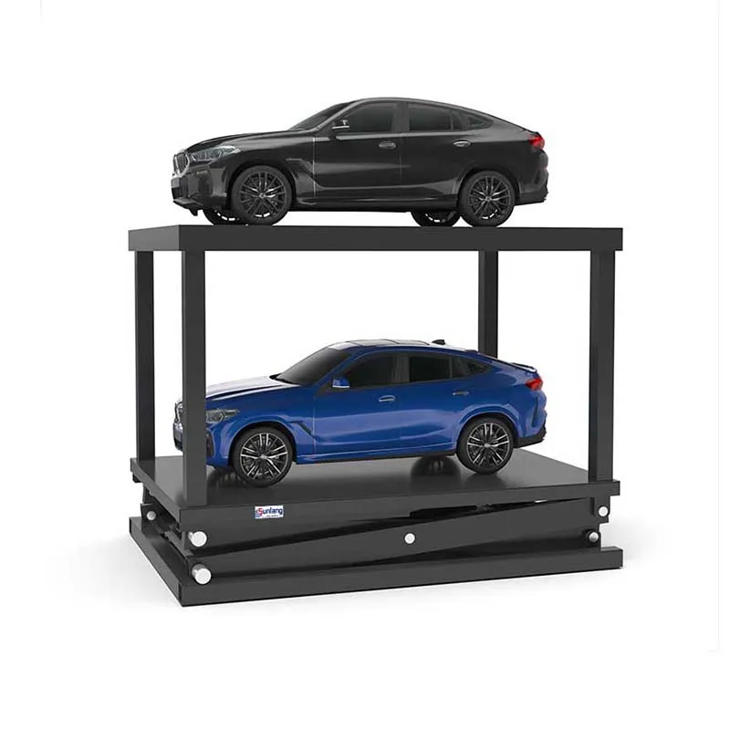
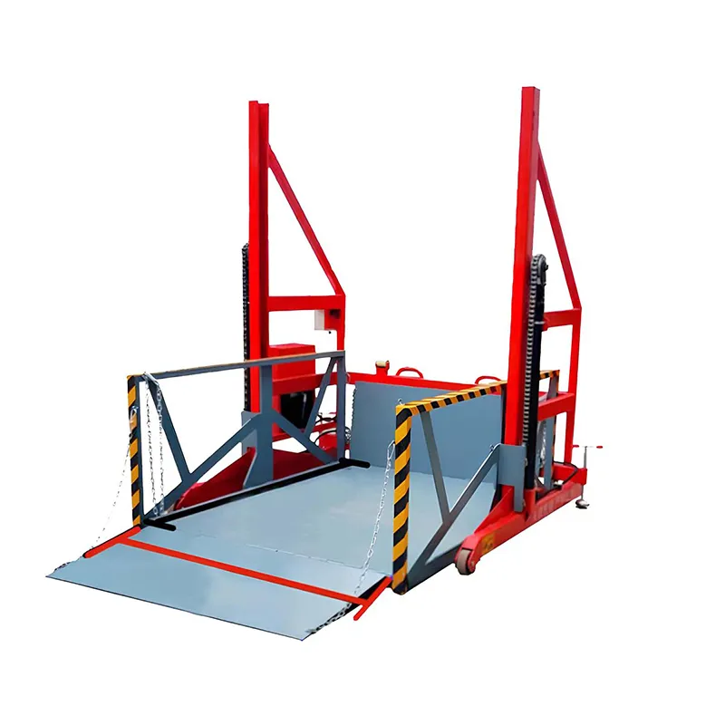
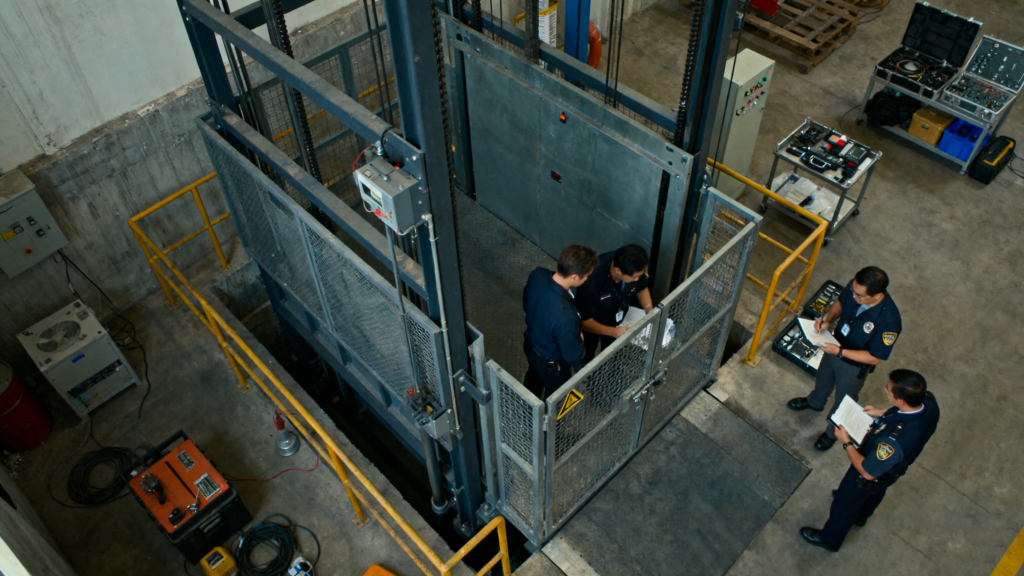
Running a precise site survey is the single most important step before ordering a cargo lift. I’ve seen projects delayed for weeks because someone assumed a pit existed, or a door opening was wide enough, or the shaft was plumb. Get the survey right and you avoid costly rework, long installation waits, and mismatched equipment. Below is a practical, engineer-led guide I use when surveying shafts and clearances — written for procurement managers, operations leads, and installers who need a reliable RFQ package.
What exact dimensions should I measure for shaft width, depth and travel height?
Measure the fundamentals first, and measure them twice. The cargo lift vendor sizes the platform, guide rails, and gates from these core numbers.
My checklist:
- Shaft internal width — measure between finished wall faces at several heights (top, mid, bottom).
- Shaft internal depth — front-to-back clear distance, again at multiple elevations.
- Finished floor to finished floor heights for each landing — these give you the travel rise per stop and total travel.
- Clear headroom above the highest landing (ceiling to finished floor) — needed for gate/drive clearance and any headroom devices.
- Pit depth (if present) from finished floor down to pit base — note whether pit bottom is concrete, rubble, or sump.
Tools I rely on: laser distance meter for verticals, 5–10 m tape for horizontals, and a plumb / level to check alignment. Record both metric and imperial units if your team or the supplier uses mixed specs.
Which door, sill and approach dimensions must I record for my RFQ?
Doors are the operational interface — get door-related dimensions perfect or your gates and conveyors won’t line up.
Include for every landing:
- Finished clear opening width and height (door reveal).
- Sill thickness and elevation relative to finished floor.
- Distance from door face to the nearest obstruction (columns, racking, guardrails).
- Approach depth in front of door for forklift or pallet jack maneuvering.
Photograph each door from the approach side, with a tape or ruler visible in-frame, and annotate the photo with the measured values. Suppliers and engineers should be able to check gate designs from your annotated photos and drawings alone.
What tolerances matter most for my installer later?
Tolerances determine how well the assembled lift will level, how gates align, and whether buffers fit.
I treat these as critical:
- Floor flatness across the pit/landing: target ±3–5 mm depending on cargo lift class.
- Pit depth tolerance: typically ±5 mm — small errors can mis-position buffers and anchors.
- Shaft plumb / wall out-of-square: record lateral deviation per meter and total drift over the height.
- Door opening tolerance: allow the supplier’s mounting plates and gate frames to fit without onsite cutting.
Ask your supplier for their installer tolerance guide and cross-check your measurements to that specification before fabrication.
How do I document floor flatness and pit depth so installers trust it?
Installers want verifiable, repeatable measurements — not estimates. Produce simple, trustworthy outputs.
How I do it:
- Create a grid over the pit/landing (e.g., 1 m × 1 m) and measure deviation from a reference plane at each grid point using a laser level or digital level.
- Produce a flatness map (sketch or spreadsheet) showing min, max, and net variation.
- For pit depth, measure at least the four corners and the center; tabulate results with labels (Corner A, B, etc.).
- Take clear photos of the pit with the measuring device visible in the frame.
Deliverables for RFQ: a one-page flatness summary, a pit depth table, and supporting photos. This saves time in FAT/SAT planning and prevents surprises.
What photos and angles should I capture for my RFQ?
Photos turn numbers into reality. I always collect a standard photo set that tells the whole story.
Minimum photo set:
- Wide shot of each landing showing door, immediate approach and floor markings.
- Close-ups of doorsills, frames, and any obstructions.
- Pit interior: shots of each corner and the center.
- Overhead/ceiling photos to show beams, pipes, or ducts.
- Power supply and control-panel locations with surrounding clearance.
Label every photo (e.g., “Level 2 — Door B — Approach from South”) and link them to the measurement spreadsheet.
Which obstructions and utilities must I note during the survey?
Hidden conflicts are the top reason for late changes. Note everything that could block rails, cylinders or panels.
Must-record items:
- Structural beams and lintels intersecting the shaft.
- Ductwork, sprinkler risers, pipes and electrical conduits near the shaft walls.
- Embedded sleeves, anchors or previous fixings in the pit or shaft walls.
- Proximity of HVAC diffusers or other service penetrations that might foul door operation.
Dimension each obstruction to the nearest wall and include a photo. If something is close to the installation envelope, flag it in red on the layout drawing.
How do I verify shaft vertical alignment and why does it matter?
Wall straightness (plumbness) directly affects guide-rail alignment and long-term wear. Small deviations compound over height.
Verification steps:
- Use a laser plumb or long plumb line from top to bottom.
- Measure lateral deviation at 1–2 m intervals and produce a deviation table.
- If deviation exceeds supplier tolerances, document it and ask the supplier whether shims, custom brackets, or a different rail method are needed.
Record the readings so the manufacturer can design rail brackets and anticipate installation shimming.
Do I need a layout drawing to confirm interfaces before fabrication?
Yes — a simple annotated layout is essential. It’s the contract between civil works, electrical, and the lift supplier.
Layout must show:
- Pit dimensions and reference levels.
- Door opening elevations and sill details.
- Power panel and cable entry points with route suggestions.
- Control pendant/cabinet mounting area and service access.
- Crane/unloading routes for installation.
Provide a PDF plus DWG if possible. Require a supplier dimensional confirmation before steel is cut — this step eliminates most site issues.
What environmental and operational details should I record?
Environmental context affects material selection, seals, and maintenance schedules.
Include:
- Ambient temperature range and humidity.
- Whether the shaft is exposed to washdown, chemicals, or outdoor weather.
- Typical forklift models and approach speeds.
- Lighting and ventilation inside the shaft.
These details help define coatings (galvanizing, paint), IP ratings for controls, and maintenance intervals.
What final checks prevent fabrication and installation delays?
Before issuing the RFQ or approving fabrication, run this quick pre-shipment checklist I always use:
- Cross-check every measurement with the installer’s tolerance guide.
- Ensure pit drainage and waterproofing are shown on drawings.
- Confirm electrical supply and cable entries are in place and labeled.
- Attach photos, flatness map, pit depth table, and layout drawing to the RFQ.
- Request a supplier-signed dimensional confirmation before cutting steel.
A signed dimensional confirmation from the supplier eliminates nearly all on-site surprises.
About Sunlang
Sunlang (Foshan, China) designs and manufactures custom hydraulic cargo lifts, lift tables, and loading dock ramps for B2B projects worldwide. We provide engineer-led project delivery, detailed shop drawings for RFQs, FAT/SAT support, and local installer coordination across Southeast Asia, Africa, and South America. For RFQ support or a tailored site-survey checklist
Email: service@sunlanglift.com
